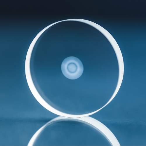
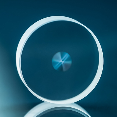
Radial polarization converter
S-Waveplate converts linear polarization to radial or azimuthal polarization and circular polarization to an optical vortex.
S-Waveplates delivery in 2-4 weeks
Technical Features
Converts linear polarization to radial or azimuthal polarization
Converts circular polarization to an optical vortex
High > 93% transmission @ 1030 nm (with AR coatings transmission > 99%)
Stand-alone – no additional optical elements needed
High damage threshold: 63.4 J/cm² @ 1064 nm, 10 ns and 2.2 J/cm² @ 1030 nm, 212 fs
Suitable for high LIDT applications and high-power lasers
Reliable and resistant surface – the structure is inside the bulk
Large aperture possible – up to 15 mm
Topological charges from 1 to 100
Wavelength from 257 to 4000 nm
Description
Fabrication of S-waveplate is based on the inscription of self-organized nanograting’s inside fused silica glass using a femtosecond laser.
Beams with radial or azimuthal polarization attract significant interest due to unique optical properties associated with their inherent symmetry. Such beams enable resolution below the diffraction limit and interact without the undesirable anisotropy produced by linearly polarized light.
S-waveplate can be beneficial in polarization-sensitive applications. For example, a radially polarized beam is more efficient at drilling and cutting high-aspect-ratio features in metals. Vector beams are also applicable in optical tweezers, laser micromachining, STED microscopy, and two-photon-excitation fluorescence microscopy.

Applications
Application examples
- STED microscopy
- Micromachining
- Micro drilling high-aspect-ratio channels
- Generate any cylindrical vector vortex
- Multiple particle trapping
- Micro-mill is driven by optical tweezers
- Use as an intracavity polarization-controlling element in cladding-pumped ytterbium-doped fiber laser for radially polarized output beam generation
Main benefits
- Allows focusing into smaller spot size (using NA > 0.9)
- Ensures the same machining properties in all directions
- Ensures the same cutting speed in all directions
- Enable ring-shaped intensity distribution in focus (at NA <0.8)
- Increases cutting speed
- Suitable for high LIDT applications
- Suitable for high power lasers
Products
Product | Wavelength | Fabricated Area | Dimensions | Thickness | Coatings | Transmission | Price | Delivery | Quantity | |
|---|---|---|---|---|---|---|---|---|---|---|
| SWP-D25.4-L3-1550-06-AR | 1550 ±40 nm | Ø 6 mm | Ø 25.4 mm | 3 mm | AR/AR | > 99% | 3600.00€ | 2-4 weeks | | |
| SWP-D25.4-L3-1550-06 | 1550 ±40 nm | Ø 6 mm | Ø 25.4 mm | 3 mm | Uncoated | > 94% | 3150.00€ | 2-4 weeks | | |
| SWP-D25.4-L3-1550-10-AR | 1550 ±40 nm | Ø 10 mm | Ø 25.4 mm | 3 mm | AR/AR | > 99% | 10000.00€ | 2-4 weeks | | |
| SWP-D25.4-L3-1550-10 | 1550 ±40 nm | Ø 10 mm | Ø 25.4 mm | 3 mm | Uncoated | > 94% | 9550.00€ | 2-4 weeks | | |
| SWP-D25.4-L3-1550-04-AR | 1550 ±40 nm | Ø 4 mm | Ø 25.4 mm | 3 mm | AR/AR | > 99% | 2300.00€ | 2-4 weeks | | |
| SWP-D25.4-L3-1550-04 | 1550 ±40 nm | Ø 4 mm | Ø 25.4 mm | 3 mm | Uncoated | > 94% | 1850.00€ | 2-4 weeks | | |
| SWP-D25.4-L3-1550-08-AR | 1550 ±40 nm | Ø 8 mm | Ø 25.4 mm | 3 mm | AR/AR | > 99% | 5550.00€ | 2-4 weeks | | |
| SWP-D25.4-L3-1550-08 | 1550 ±40 nm | Ø 8 mm | Ø 25.4 mm | 3 mm | Uncoated | > 94% | 5100.00€ | 2-4 weeks | | |
| SWP-D25.4-L3-1064-10-AR | 1064 ±35 nm | Ø 10 mm | Ø 25.4 mm | 3 mm | AR/AR | > 99% | 5300.00€ | 2-4 weeks | | |
| SWP-D25.4-L3-1064-10 | 1064 ±35 nm | Ø 10 mm | Ø 25.4 mm | 3 mm | Uncoated | > 94% | 4850.00€ | 2-4 weeks | | |
Haven’t found what you need?
Downloads
References
- Baltrukonis, J., Ulčinas, O., Orlov, S., & Jukna, V. (2020). Void and micro-crack generation in transparent materials with high-energy first-order vector Bessel beam. JOSA B, 37(7), 2121-2127.
- Rudolf Weber, Andreas Michalowski, Marwan Abdou-Ahmed, Volkher Onuseit, Volker Rominger, Martin Kraus, Thomas Graf, “Effects of Radial and Tangential Polarization in Laser Material Processing”, Physics Procedia, Volume 12, Part A, (2011), Pages 21-30. doi:10.1016/j.phpro.2011.03.004
- Cyril Hnatovsky, Vladlen Shvedov, Wieslaw Krolikowski, and Andrei Rode, “Revealing Local Field Structure of Focused Ultrashort Pulses”, Phys. Rev. Lett. 106, 123901 (2011). doi:http://dx.doi.org/10.1103/PhysRevLett.106.123901
- Yao Bao-Li, Yan Shao-Hui, Ye Tong and Zhao Wei, “Optical Trapping of Double-Ring Radially Polarized Beam with Improved Axial Trapping Efficiency”, Chinese Phys. Lett. 27 108701, (2010). doi:http://dx.doi.org/10.1088/0256-307X/27/10/108701
- Hong Kang, Baohua Jia, Jingliang Li, Dru Morrish, and Min Gu, “Enhanced photothermal therapy assisted with gold nanorods using a radially polarized beam”, Appl. Phys. Lett. 96, 063702 (2010). doi:http://dx.doi.org/10.1063/1.3302461
- Gilad M. Lerman and Uriel Levy, “Radial polarization interferometer”, Opt. Express 17, 23234-23246 (2009). doi:10.1364/OE.17.023234
- Fake Lu, Wei Zheng, and Zhiwei Huang, “Coherent anti-Stokes Raman scattering microscopy using tightly focused radially polarized light”, Opt. Lett. 34, 1870-1872 (2009). doi:10.1364/OL.34.001870
- Weibin Chen, Don C. Abeysinghe, Robert L. Nelson§ and Qiwen Zhan, “Plasmonic Lens Made of Multiple Concentric Metallic Rings under Radially Polarized Illumination”, Nano Lett., 2009, 9 (12), pp 4320–4325. doi:10.1021/nl903145p
- Gilad M. Lerman and Uriel Levy, “Effect of radial polarization and apodization on spot size under tight focusing conditions”, Opt. Express 16, 4567-4581 (2008). doi:10.1364/OE.16.004567
- D. W. Diehl, R. W. Schoonover, and T. D. Visser, “The structure of focused, radially polarized fields”, Opt. Express 14, 3030-3038 (2006). doi:10.1364/OE.14.003030
- Tasso R. M. Sales, “Smallest Focal Spot”, Phys. Rev. Lett. 81, 3844–3847 (1998). doi:http://dx.doi.org/10.1103/PhysRevLett.81.3844
- A. V. Nesterov, V. G. Niz’ev and A. L. Sokolov , “Transformation problem for radiation with radial polarization”, Volume 90, Number 6 (2001). doi:10.1134/1.1380793